Tuesday 1 May 2012

Starter Motor


Starter that I used. a M3T from a Mitsubishi engine


Today I did the workbook on starter motors which involved disassembling a starter motor and checking parts of it, by completing various tests


Starter Motor Disassembly
  1. First removed the "M" terminal wire from the solenoid. It is removed by undoing a nut and it then lifts of solenoid.
  2. Then removed the bolts in the top of the starter motor, or communicator end housing, with 12mm spanner.
  3. Removed communicator housing, then removed brushes and brush plate.
  4. Removed field coil housing, which is the main body of the starter. (the middle section).
  5. Removed shift fork then removed the armature assembly.
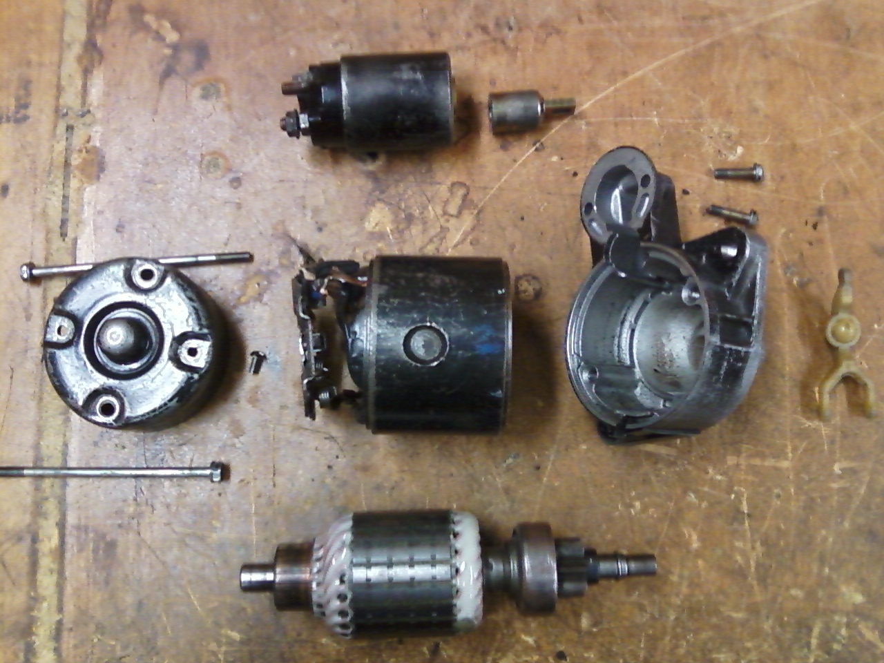
Fully Disassembled Starter Motor,
 Going clockwise: Solenoid and Plunger, Drive End Housing, Shift Fork, Armature and Clutch, Communicator End Housing and bolts, in the Centre; Field Coil Housing

Testing Performed

After I had disassembled the starter motor I began performing the tests required.
 The first test was a visual inspection of the armature and from the inspection I found that it was in good condition and no repairs were necessary. As there was no overheating, burning, physical damage or poling.

The second test was the ground circuit test which tested for short circuiting of the communicator segments, to the armature shaft. This required the use of multimeter on the Ω setting and putting the positive probe (red) on the communicator segments and the Negative probe (black) on the shaft or core of armature if not earthing I would get a reading of "OL" on my multimeter which is what I got, so it was in good order.

The third test was a continuity circuit test which required use of the multimeter again on Ω setting, but probes were placed on the communicator segments with black lead on one segment and red lead on another, then moving the red lead to each segment. When checked results were in range which was less than 1Ω so this was also okay.

Testing Alternatives

the first alternative too the previous tests required use of a communicator tester that uses a light to show continuity (below)  

Continuity tester alternative to using multimeter
 To use this required you to put the leads of the tester, onto the segments of the comunicator. One lead was put onto the main core of the armature (black) and the other was put onto the segments (red) when there was continuity the tester light remained on like in picture above.
For the ground test all that was needed to do was turn of switch and test again making sure the light does not glow. The tested armature passed these tests.

The second alternative was the use of the growler tester  

Growler tester and armature tested
This was used to check for short circuiting of the armature. The growler creates a electro-magnet that produces the magnetic field of the armature. Then a hacksaw blade was used to detect if there was any variations in the field by being held above the armature and then  vibrating if a winding of the armature is malfunctioning and shorting. Tested armature was in good condition here as well.

Both testing machines that were used. Growler to right and Continuity tester in middle and left
  Field Coil Testing 

The field coil also required testing this was done with the multimeter on the Ω setting and checking for continuity and grounding. 
Testing for continuity required me to put the negative lead on the earth and the positive lead on a brush. This showed a reading of 0.00Ω which was okay for the starter I tested, as required was 0 - 0.05Ω 
Testing for grounding required putting the positive multimeter lead on the M terminal wire and the negative lead onto the housing. When I tested this I got a reading of 8.5MΩ which was incorrect for the field coil. This meant  that the current was earthing before it should. The reading should have been OL this meant that a wire in the field housing was broken and the starter or the field coil housing need replacing. But it was not a serious problem as starter still functioned.  

Solenoid Testing

The final tests required were of the solenoid. This required use of a 9V power source and wires connected to the B and S terminal of the solenoid  

Solenoid Terminals
This checked if the plunger of the solenoid was working correctly. The first test was the pull in test. The plunger is meant to pull in when the negative wire is connected to the B terminal (starter motor supply terminal) and S terminal (battery supply) to show plunger is working correctly, which it was.

The second solenoid test was the hold in test this test shows if the plunger is remaining in when the power source is connected to ignition terminal M and a negative wire to the solenoid body. When the power source is disconnected plunger should release. This was okay also.

Final Test 

This test was done after I reassembled the starter this was assembled by going in reverse order to disassembly. 
After It was reassembled I completed the no load test which required connecting starter to a 12V battery and running it and recording the current flow. To do this the starter is held in place with a special vice and  2 wires were connected between the battery supply terminal (B) and a second cable to negative battery terminal. Then a 3rd wire connected from the M terminal to S terminal to run starter.  

Starter connected to Battery
Once it was running I used a clamp meter, set to 200A and connected it around the positive lead from the battery and got a reading of 58.2A at 11V. This is the amount of current being drawn from the battery to power the starter motor. This was above manufactures specifications which was 30A - 50A Indicating starter was worn.


Testing completed.

Monday 30 April 2012

Battery, Alternator and Starter On Car Testing


My car was used for battery and alternator testing it is a
1991 Toyota Corolla AE92.
Battery Testing


Today I completed the on car testing workbooks. I used my cars battery for the testing and from the various tests I concluded that it was in good working order. Testing that was done Involved using a Multimeter, load tester and digital battery tester.


Multimeter was used for:
  
Obtaining open circuit voltage (OCV): This was done by first removing surface charge on the battery, by turning on the head lights for 1 minute, with meter connected across terminals (reading should fall). Then after turning the headlights off checking once again with meter on DC voltage until reading stops rising. When I checked I got a reading of 12.65V which indicated a 95% charged battery which was good.  


Finding Parasitic Draw: This was done by connecting the meter in series on Amp setting by disconnecting negative battery terminal and adding the meter with positive lead (Red) on negative lead and meter negative lead (black) on negative battery terminal. This is used to find out how much charge is being used by accessories when car is not running. The tested battery showed a reading of 2.62mA being used. So it was well within correct range which was 35mA or less.   


Load Tester was used for: Determining the batteries ability to provide cranking voltage. It required you to find out what load current was required which for my battery was 215CCA as my batteries normal CCA (cold cranking amps) was 430CCA Correct voltage was found by 430/2=215. When tested the reading on the voltage was 10V which was correct for the battery.


Digital Battery Tester was used for:  Instead of doing all the above tests as it obtains all readings in the same unit and is much easier to use and obtain readings. 

Picture of Digital Battery tester similar model to what I used today

When I tested my battery I had to change the rating on the tester to 430CCA and then push the "test" button. It completed the test and stated on the screen that the battery was a PASS. It also found the OCV which was 12.71V and the current CCA which was 400CCA Which meant that the battery was fully charged and in good working order.

Alternator On Car Testing

Alternator that was checked
I did this using the alternator of my car and by using a Multimeter set to volts and a Clamp meter to obtain the current moving through a conductor from the battery to alternator.
When checking the alternator voltage regulator I found that it was working correctly it showed on my meter a reading of 14.5V which meant that the voltage regulator was working correctly. This is checked by turning the car on and then letting it run, while running I put the multimeter across the positive and negative battery terminals and then recorded the reading.

For the next part the clamp meter was used to get the no load amps this was done by putting the clamp around the main lead to the alternator and then recording the reading which was 13.6A which was also correct Indicating It was in good order.

Starter On Car Testing


This required testing of the various circuits of the starter motor while engine was cranking to determine voltage drops.

  • First area tested was loss between the batteries positive terminal to the starter solenoids input stud. Got a reading of 120mV 
  • Second was across both of solenoids studs which also got 120mV 
  • Third was between positive battery terminal and the starter motors body which got 111mV 
  • The maximum voltage drop was 351mV this was determined when earlier readings were added together 

From these readings I found that the starter motor was also in good condition as none of the maximum voltage levels were exceeded meaning that no repairs or replacements required.


Friday 27 April 2012

Today I completed the alternator testing. The next part that was tested was for stator winding continuity which required use of the multimeter once again. 


To do this I was required to find the neutral point. This is identified by the terminal that had the most wires attached. I found this by checking the size of the terminals and the largest was the neutral point.  
Picture showing neutral point. It was much larger
than the other terminals

After this was found the black lead of the multimeter was put onto it and the red lead was put onto each of the other terminals, then the resistance was checked. The results were all within manufacturers specifications which 0.0Ω to 0.2Ω and required was <1Ω.


Stator winding earth leakage was also tested this way but instead of black being on the Neutral terminal the red lead was and the black lead was placed onto each of the other terminals.The meter showed a reading of "OL" which was correct because if it showed a resistance it would mean that the wires have shorted and will need replacing.


Rectifier Diode Testing
The next part that was tested was the rectifier diode. This Required a multimeter as well with each lead placed on the terminals of the diode. 

Rectifier Diode being tested. black lead was placed on the "B"
terminal and red was placed on each of the "P" terminals like above


From this I found that it was in good condition as each terminal tested showed a value of 0.47V to 0.49V which was within specification which is 0.4V - 0.8V. I also tested it with red lead on terminal B and black lead on the P terminals and It was within specification also which was high voltage or "OL".


Rectifier Negative Diode Testing
The next area that was tested was the negative diodes of the regulator. This required the red to be put on the E terminal and the black lead on the P terminals. When tested the meter showed "OL" also which means voltage was high like it was meant to be.
Then the leads were switched so black was on E and red lead on P and this showed correct voltage also which was 0.46V - 0.48V and required was 0.4V - 0.8V


Picture taken from workbook showing terminal names


Voltage Regulator Testing
The last test required use of the Transpo Regulator Tester to test the alternator regulator.
The voltage regulator controls the amount of voltage put out by the alternator which is meant to be around 14V and no more as the test showed.  


Using the Transpo regulator tester to test regulator.
The test required several leads to be placed onto the correct terminal points and the Transpo tester to be switched onto field setting A, like in picture above. Once the Transpo tester was correctly connected to the regulator I found that it was working correctly with proper lights showing and correct voltage displayed which was 14.4V. 

Thursday 26 April 2012

Alternator


Today I began work on the Alternator testing book. The first thing I did was disassemble it. I removed the rear cover nuts with a 8mm spanner and removed cover 


Rear Cover Removed shows nuts and terminal insulator bottom right 


After the cover was removed I began to remove the other parts that are on top which were the brush holder ,voltage regulator, and Rectifier, all came out fairly easily once the correct screws and nuts were removed. 


Fully disassembled rear of alternator. shows parts removed (going clockwise) bottom right is Regulator, next part above to left is Rectifier, and to the right of that is the Brush holder and brushes, at the very top is the screws and nuts that are removed


After this was done I began on the testing of the alternator. The first area I tested was for earth leakage. Which requires you to use a multimeter on resistance (or Ω) test position. The probes had to be put on the centre of the rotor. The black lead was put on the centre of the shaft and the Red lead was put on the slip ring (at base of shaft) when I read the reading it showed OL which was what it should read, so it passed.


The next test was for Rotor Winding Continuity. Which required me to put each lead of the multimeter, on the slip rings one above the other. When the reading was complete it showed a reading of 2.76Ω which was inside the required value which was <5Ω so it passed.


That is all I did today tomorrow I will complete the testing of the alternator.

Wednesday 25 April 2012

Electrical Components


Over the past 3 weeks I have been doing work on electrical components this is what I have learned.


Cathode on left Anode on right
Diodes: When we went over diodes I found that they are used to Prevent current going in the wrong direction in a circuit. this is called reverse bias the arrow in the symbol shows which way the current is being stopped from flowing each end is differentiated by one being a cathode and the other a Anode  
I also found when I tested one with a Multimeter that it only gets a reading when its tested from anode to cathode meaning current is only flowing in one direction.


Resistors: The main thing I learned from resistors Is how to get what there rating is from the coloured bands on the resistor. the first 2 bands are the starting numbers and then the following band is how many zeros are added to the earlier numbers and then you get the reading in Ohms eg. 


This resistor is 2000 Ω Because the first red band means the number 2, the black band means the number 0 and the last red band is the number of zeros to add on which being red means 2 so 2 zeros are added getting the value.

I also tested two resistors in series and parallel circuits by combining them together and found when they are in series one after the other the total resistance is added together and when in parallel the voltage is split evenly between both resistors. The same as circuit using light bulbs.

Tuesday 3 April 2012

Completed My logic Probe today and it is working well. The first thing I did was improve my soldering from the first attempt, because I found it difficult to add the small heat shrink over the top of the positive and negative wire to protect the soldering of the LED and resistor 


Close up of the heat shrinking that is over the resistor and LED
 on each wire you can see the bulge from the resistor underneath
the Red heat shrink is holding the parts in place
The next thing I did was grind the tip into the brass rod to make the point of the probe and then cover it in black heat shrink, to prevent the current earthing before it can be checked. I then joined it all together and held it in place with the red shrink.
After that I wound the LED legs around the rod, on the brass that was kept exposed to hold LEDs in place.


LEDs, brass rod, and wires held together with shrink. Also shows how LED legs
were wound around rod
The next part I did was cut a slit into a piece of clear tubing to protect the wires from damage. Before I covered it I soldered the LED legs in place and found that it was short circuiting because the LEDs were to close together. Meaning that only 1 LED was going. After I moved them apart it worked fine.

Once it was okay I slipped the clear tubing over the top of the wires and heat shrink. Then got the 10mm heat shrink and also slipped that over the top of the clear tube, then shrunk it in place, with a heat gun. After adding a few extra pieces to improve its appearance It was completed and working correctly.
  
Completed  logic probe 10mm heat shrink over the top of clear tubing and first 
lot of heat shrink
Probe showing positive flow green LED is on
Probe showing negative flow red LED is on
Probe working when no current is being tested both LEDs on

Friday 30 March 2012

Today I figured out how to wire a circuit in Series Parallel I found it was possible by first wiring  2 bulbs in parallel and then add in the series bulb. so 3 bulbs are running 
3 bulbs running in series parallel
Close up of wiring in series parallel. Power is drawn from right of image and
returns back by bottom left black wire

I also completed the workbook and found that in this layout the bulb that is wired in series uses most of the voltage and glows brightly, then when it reaches the parallel bulbs it gets split in evenly and glows dimly between the two bulbs.
I also found with the calculations, that they are a lot easier then I first thought as long as you have  the correct data and know the correct formula for what you are working out. 


This completes the Practice on Electrical circuits.


Logic Probe Construction 
Also today I began Work on building a Logic Probe that will be used in the Fuel systems practical.
I completed the first step in building a probe, which was soldering a 1K ohm resistor and a red LED to the black wire and another 1K ohm resistor and a green LED to a red wire.
Showing LEDs, Resistors and Wires soldered together
The part where I had to be most careful was getting the LEDs around the correct way, as there is a positive and negative terminal on them. you can tell this by the length of the "legs" 


Picture showing length  of legs  Longer one or the anode is +
 and shorter one or (k)cathode is -  
 on the red wire the shorter leg is soldered and on the black wire the longer leg is soldered to the resistor.


On Tuesday next week I will complete the probe.